⚡ DIY Power Factor Controller with Pico W
Explore Power Factor Correction (PFC) with this experimental Homatica project by Claudio Cabete. Using Raspberry Pi Pico W, learn zero-cross detection, PWM shaping, and voltage feedback to optimize AC power draw in a DIY setup.
🔍 Why I Built This PFC Controller
Power supplies often draw electricity in short, inefficient bursts, stressing the grid and requiring oversized wiring. I wanted to understand Power Factor Correction (PFC)—a technique to smooth power draw—by building a controller from scratch. This project is a learning journey, using the Pico W’s capabilities to experiment with real-time AC synchronization and efficient power management. It’s part of Homatica’s mission to explore DIY home automation with curiosity and open-source tools.
💡 What is Power Factor Correction?
Power Factor Correction (PFC) makes electrical devices draw power smoothly, reducing waste and grid stress. Instead of erratic bursts, PFC aligns power draw with the AC waveform, lowering peak current and enabling thinner wires. Think of it as turning chaotic water splashes into a steady stream—better for efficiency and infrastructure. This project experiments with PFC using a Pico W to control AC power draw in real time.
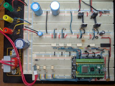
🧰 Hardware Setup
- Raspberry Pi Pico W: Runs MicroPython for real-time control.
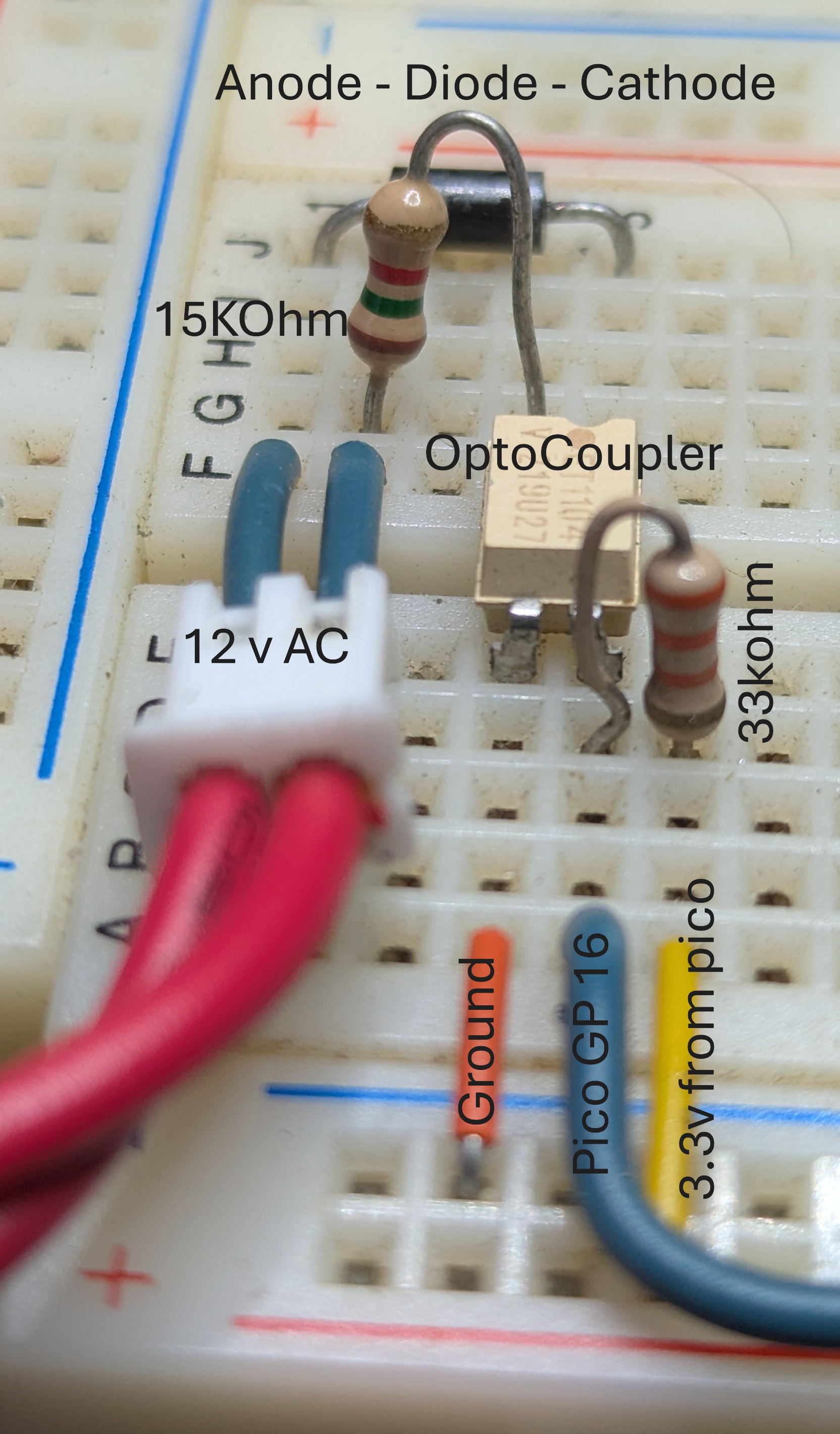
- Zero-Cross Detection Circuit: Uses a resistor, diode, and opto-isolator for AC sync.
- PWM Output: Connected to Pin(19) for shaping power draw.
- Voltage Feedback Circuit: Provides adaptive control via analog input.
🧠 How the PFC Controller Works
The system detects the AC voltage’s zero-crossing point using an opto-isolator circuit, syncing the Pico W with the AC sine wave. A precomputed Lookup Table (LUT) shapes PWM output to mimic a sinusoidal power draw, reducing harmonic distortion. An interrupt-driven update_pwm() function, optimized with @micropython.viper, updates the PWM duty cycle in real time. A secondary PWM on Pin(19) acts as a sampling clock for precise timing.
A voltage feedback loop adjusts the duty cycle dynamically, ensuring efficient power draw. Explore the code on GitHub.
🔧 Technical Highlights
- Real-time AC waveform synchronization using zero-cross detection.
- Dynamic PWM shaping via a 200-item LUT for smooth power draw.
- High-precision timing with
@micropython.viperfor sub-millisecond control. - Adaptive voltage feedback loop for efficiency.
- Debugging hooks for oscilloscope visualization.
Sample MicroPython Code
import machine
import utime
import math
import array
import micropython

# Zero-cross detection
zc_pin = machine.Pin(16, machine.Pin.IN, machine.Pin.PULL_DOWN)
last_zc_time = 0

def zc_callback(pin):
    global last_zc_time
    last_zc_time = utime.ticks_us()
    print("Zero-cross detected!")

zc_pin.irq(trigger=machine.Pin.IRQ_FALLING, handler=zc_callback)

# Lookup table for PWM shaping
lut_items = 200
lut = array.array('H', [0] * lut_items)
for n in range(lut_items):
    theta = n * math.pi / (lut_items / 2)
    duty = 0.25 + (0.5 - 0.25) * (1 - math.sin(theta))
    lut[n] = int(duty * 65535)

# PWM setup
pwm = machine.PWM(machine.Pin(19))
pwm.freq(20000)  # 20 kHz sampling clock
lut_index = 0

@micropython.viper
def update_pwm(pin):
    global lut_index
    pwm.duty_u16(lut[lut_index])
    lut_index = (lut_index + 1) % len(lut)

# IRQ setup
pfc_sense_pin = machine.Pin(16, machine.Pin.IN)
pfc_sense_pin.irq(trigger=machine.Pin.IRQ_FALLING, handler=update_pwm)

# Voltage feedback
fbl = machine.ADC(machine.Pin(26))
target_voltage = 3.3
k_p = 0.1
duty_scale = 100

def feedback_loop():
    voltage = 3.3 - (fbl.read_u16() * 3.3 / 65535)
    error = target_voltage - voltage
    global duty_scale
    duty_scale += int(k_p * error)
    duty_scale = max(10, min(duty_scale, 1000))
📊 Features
- Real-time AC waveform synchronization.
- Adaptive duty cycle control via voltage feedback.
- Lookup table for smooth power draw.
- Debugging hooks for scope visualization.
💡 Lessons Learned
- Simple components like opto-isolators enable powerful control.
- AC synchronization requires precise timing and debounce logic.
- MicroPython on Pico W handles real-time tasks effectively.
📈 Next Steps
I’m refining the feedback loop for better stability and planning to add Home Assistant integration for real-time monitoring. A full schematic and tutorial are coming—stay tuned on my blog!
Want to try this? Visit the GitHub repo or discuss on r/homeautomation.